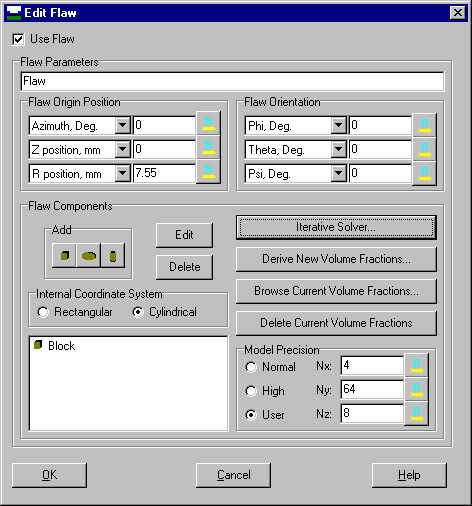
The flaw form enables a user to add, remove or edit a flaw. Let's click on the "Use Flaw" checkbox to add and edit our flaw.
The flaw will be centered at Z = 0 in the global coordinate system. Hence, the "Flaw Origin Position" will be: "Azimuth"=0; "Z position"=0; "R position" = 7.55 (recall the dimensions of the problem, and the location of the flaw in the initial problem configuration).
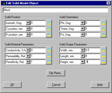
Next, click on the "Block" speed button in the "Add" group box of the "Flaw Components" group box. We will model the slot as a "block" of air in the otherwise unflawed workpiece. We position this block relative to a flaw coordinate system, in the same way that we built the probe by placing a coil relative to the probe coordinate system.
Since the slot is empty, the "Solid Material Parameters" within the Block has the properties of air: "Conductivity"=0; relative "Permeability"=1; relative "Permittivity"=1.
The "Solid Shape Parameters" are set to the flaw dimensions: "Width"=0.5, "Length"=8, "Height"=0.9.
Press "OK," in order to return to the Edit Flaw form, and choose the "User" radio button in the "Model Precision" group box, in order to customize the grid for the flaw model. Enter "Nx"=4, "Ny"=64, "Nz"=8 in the appropriate edit boxes.
When the flaw form is finished, click "OK" to accept the edits, then, back at the main form, choose "Analyze | Run!" to analyze the problem. Be aware that we have configured a problem with 5,344 unknowns, and that the Direct Solver, which you have chosen by default, will require 218MB of memory to store its system matrix. Further, the Direct Solver will spend some time decomposing this matrix while computing the response. If you do not have sufficient memory to solve this problem with the Direct Solver, then you must choose the "Iterative Solver" in the Edit Flaw frame, and check the "Use Iterative Solver" checkbox.